Small Power Amplifier Build
-
10 September 2025 |
-
13 September 2025 |
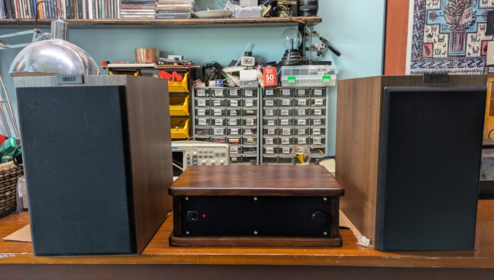
I built this power amplifier recently for a friend of mine. It’s a “moderate power” ESP P3A that’s intended to drive a pair of bookshelf speakers.
It’s been quite a while since I’ve undertaken a project like this and I found I had to re-learn a bunch of things while doing it. But it’s been a lot of fun and I really enjoyed working on it.
The Chassis
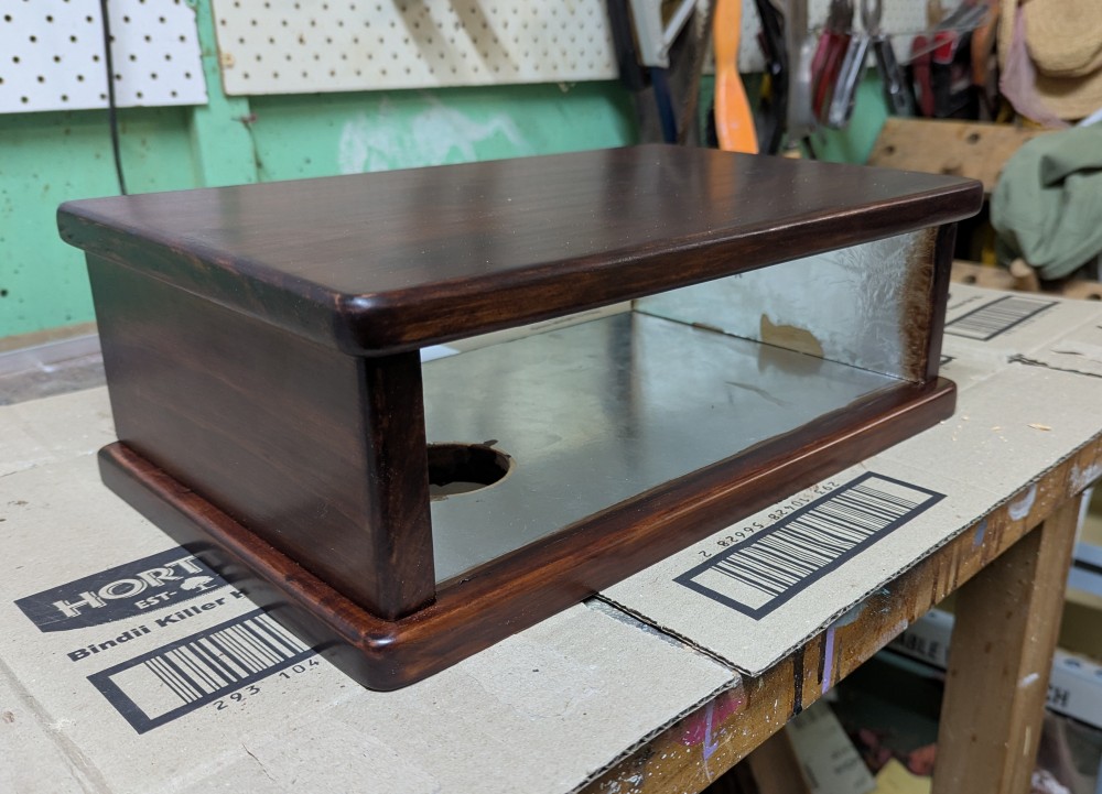
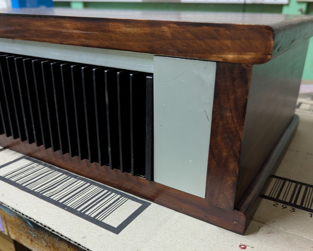
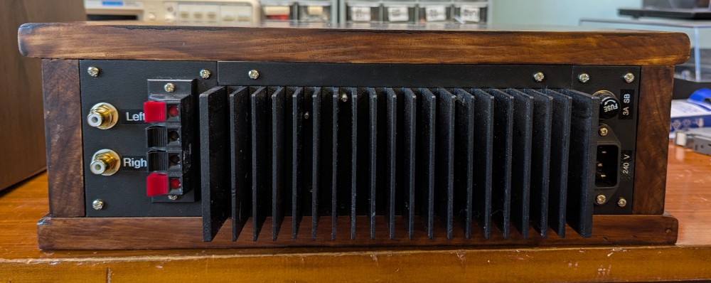
The chassis design is very similar to the one from my guitar amplifier but this time I opted to have the heasink hanging off the back rather than more integrated into the box. This made construction a little easier and I don’t mind doing it on hi-fi amps because they generally sit in one place all the time, whereas guitar amplifiers tend to get moved around a lot and might suffer the odd knock.
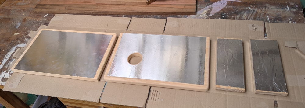
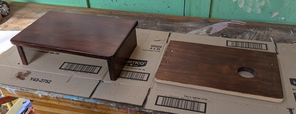
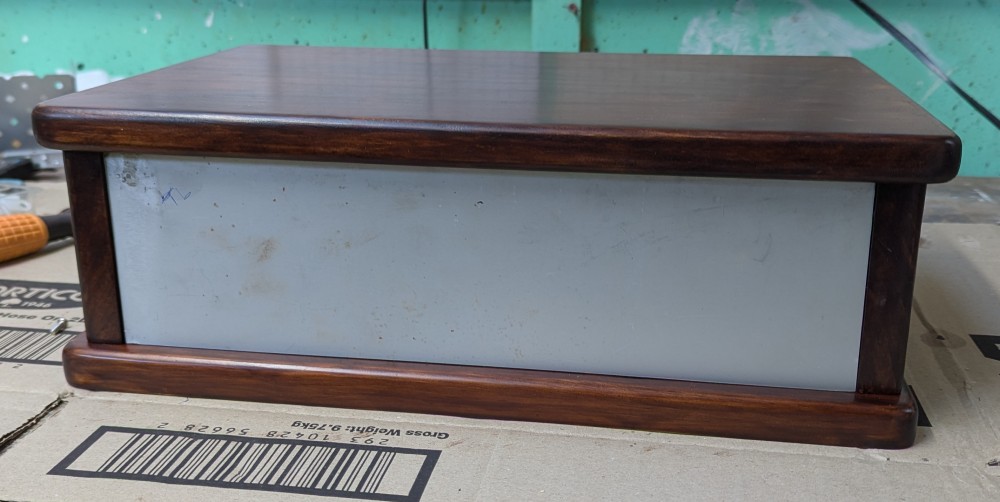
The chassis is made from simple pine from the local hardware shop. I rounded off the front corners and put a bull-nose on the edges with a router to soften its appearance a bit.
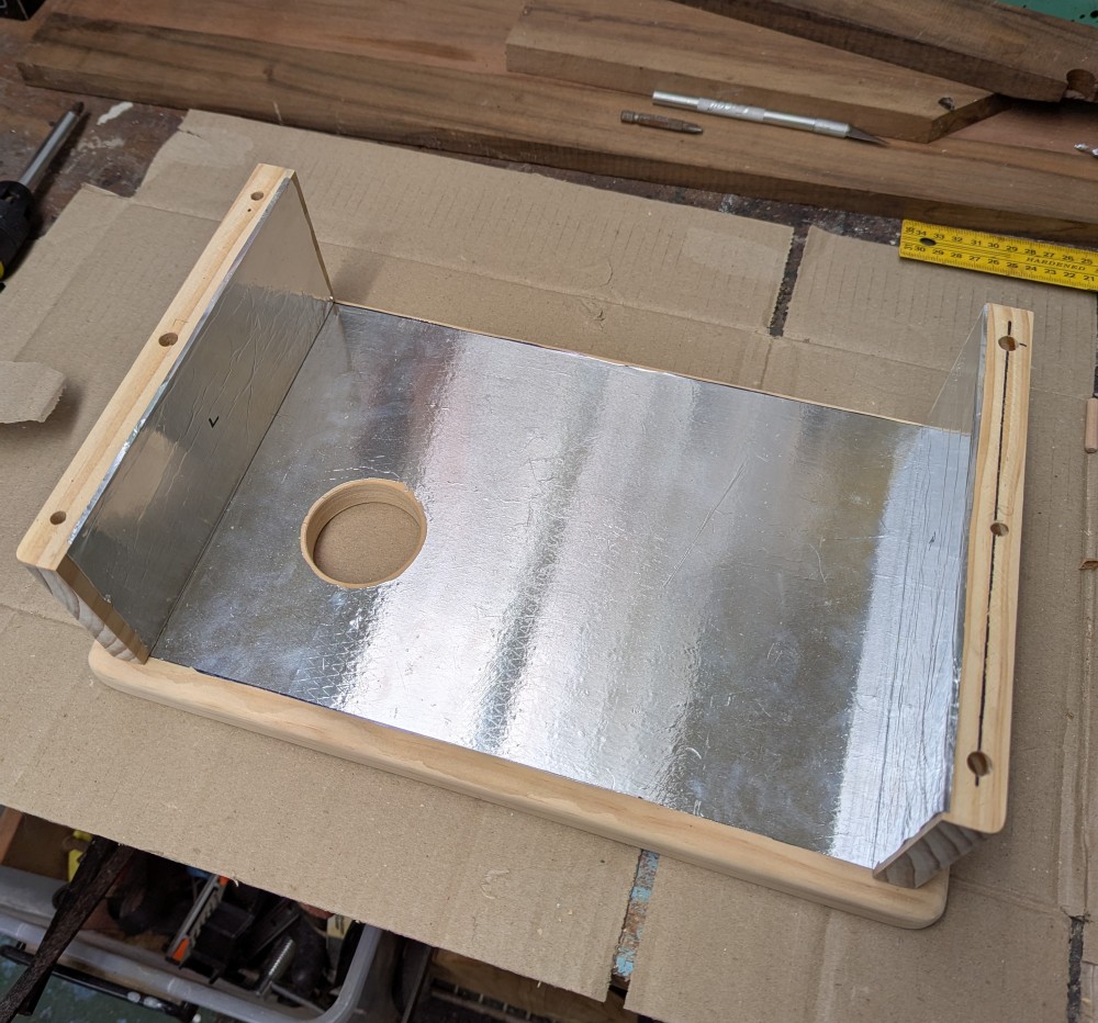
The insides are lined with aluminium foil to create a Faraday cage around the electronics. To do this, I paint the timber with a very light layer of heavily-watered-down (>10:1) PVA wood glue, apply the foil and smooth it out, before trimming away the excess with a hobby knife.
As with my guitar amplifier, the bottom of the case holds the electronics and the top and sides are joined permanently to form a kind of “lid” that screws down over the whole assembly.
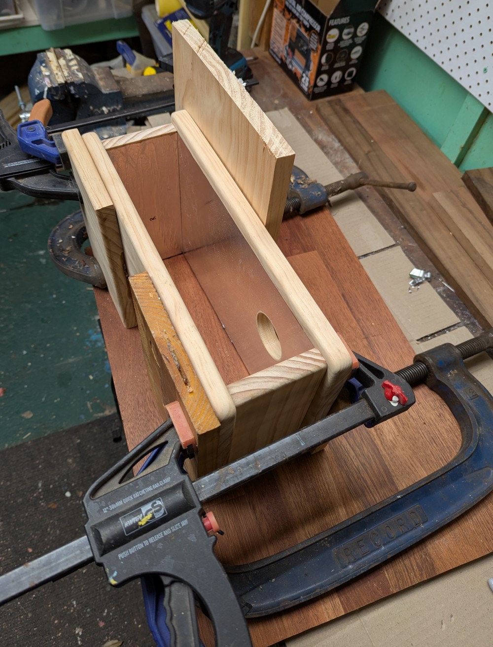
I finished the outside with a satin-finish “chocolate walnut” all-in-one varnish and stain combination. I found this to be difficult to apply and had to thin it out a bit with turpentine to be able to get an even coat. After several coats, I think it’s come up rather well.
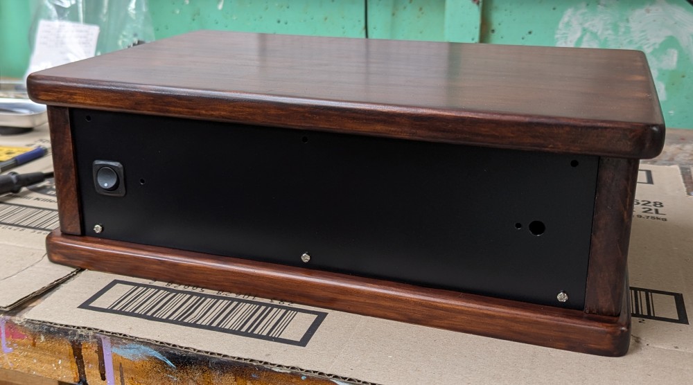
The front and rear panels are made from 2mm aluminium sheet that are cut to size and fixed to two pieces of aluminium angle that run along the inside top and bottom of the box.
Once the panels are drilled, I use them as templates to mark the positions of the drill holes on the angle bracket and then drill and tap 3mm thread into the bracket. It’s fiddly work.
I painted the panels with two coats of satin black and one coat of satin clear spray paint. I was very happy with the paint jobs for these, they’re very even and look almost professional.
The Electronics
I used to make power supplies using blank PCB material and “etch” tracks out by using a Dremel to score the copper from the board, but I found it to be a fiddly and annoying method of construction. It’s difficult to plan how the components themselves will sit on the board with nothing to use as a reference point.
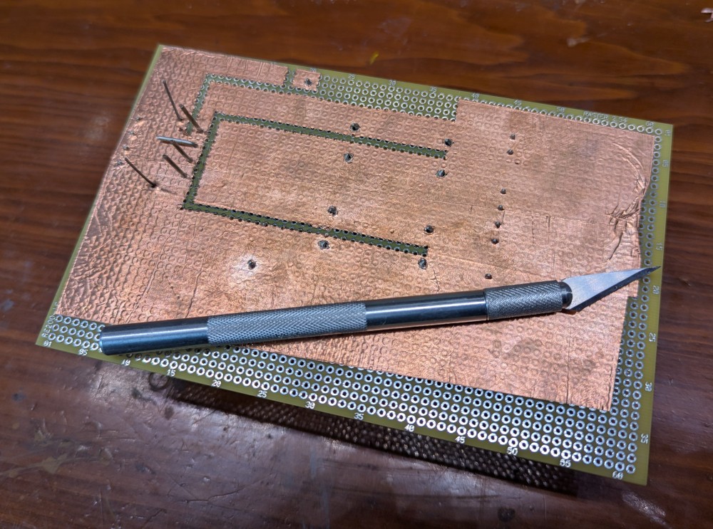
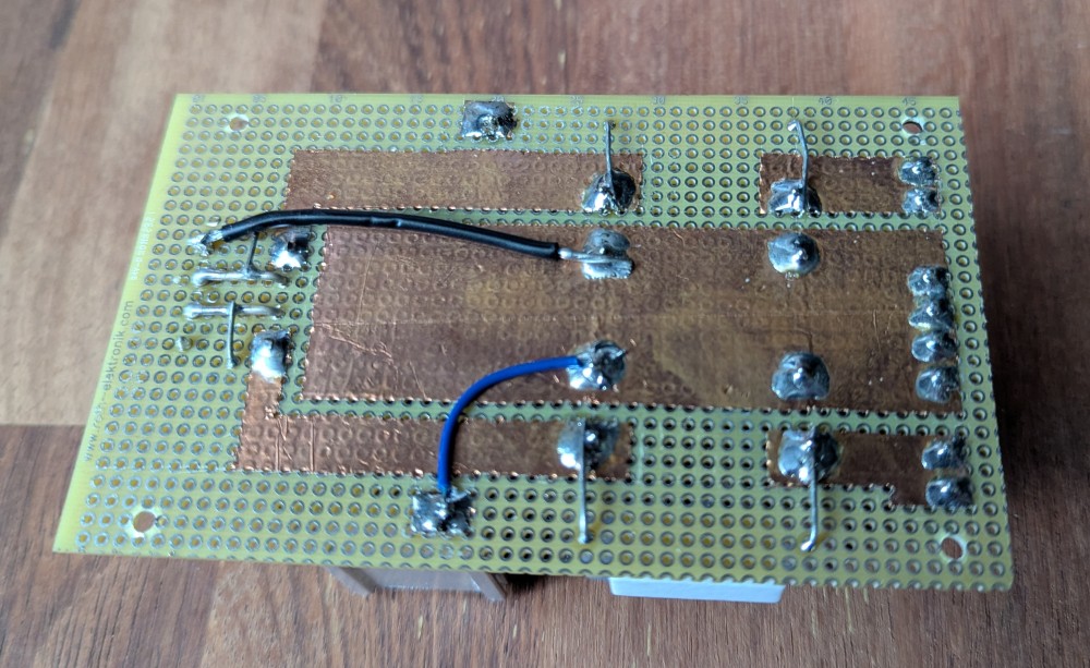
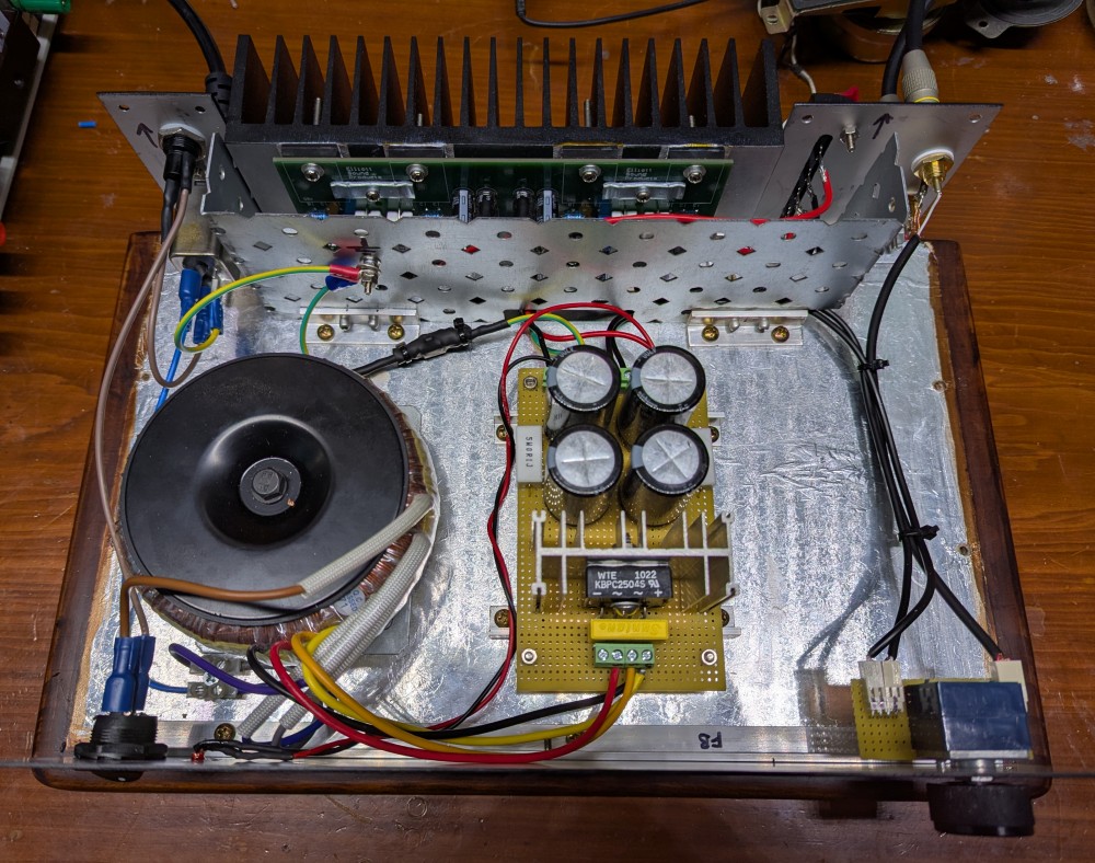
Now I make them by covering a piece of prototyping board with adhesive copper tape and cutting away excess material to create tracks as I go. I find this to be a much easier way of doing it because the prototyping board has pre-drilled holes I can use for component alignment.
The amplifier itself was easy enough to assemble. I purchased the bare PCB from ESP and simply stuffed it with components.
The first test was performed using my benchtop power supply at a fairly low voltage to limit damage should something go wrong.
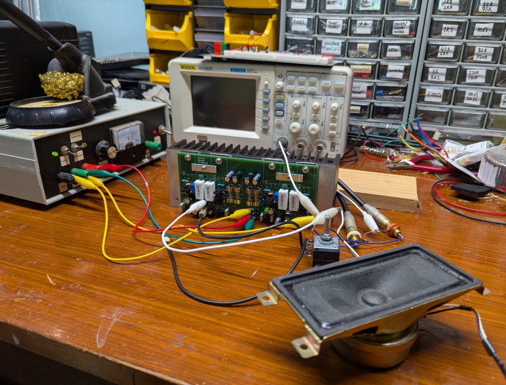
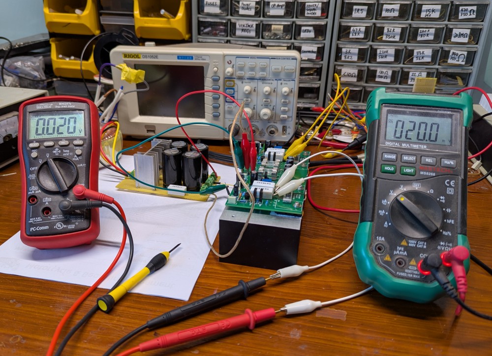
Once initial testing of the amp verified that it worked, it was time to set the bias current in the output transistors. To do this, I needed to use the amplifier’s own power supply as my bench supply is not capable of delivering the required voltage.
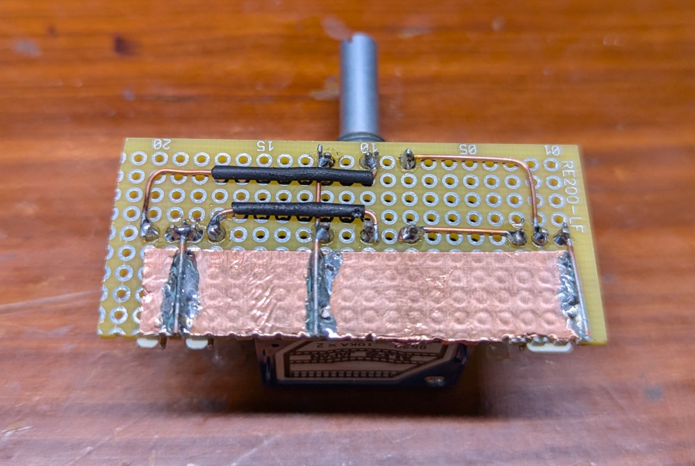
I wouldn’t normally include a level control on a power amp, but this is for a friend and will be used differently to my own setup.
Final Assembly
Once the electronics were all tested and working, it was time for final assembly of the unit.
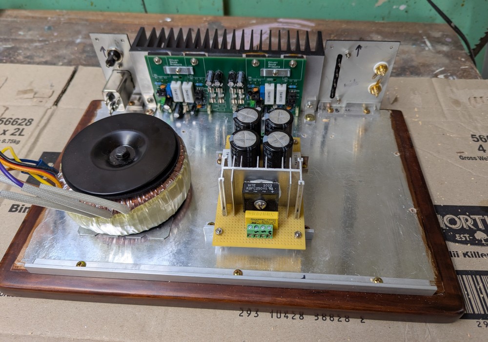
The bridge rectifier heatsink is made from one I pulled out of an old PC power supply. I simply cut it down to the same height as the reservior capacitors.
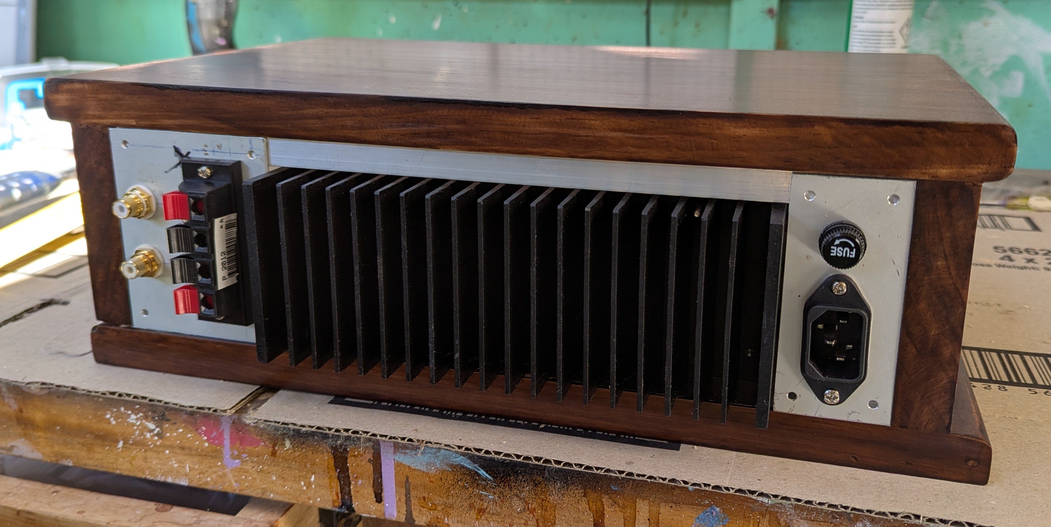
I decided not to add any labels to the front panel. I like the clean look and I think it’s all pretty self-explanatory anyway. I did add some labels to the rear as they are important - especially the fuse and voltage rating. The labels were made with a label maker and I discovered that you can get white-on-black tape for them, so that was quite nice.
Here it is working and ready for delivery to my friend. I’m really happy with the way this turned out. There were a few moments along the way where things weren’t going so well and I was worried I’d made a bit of a mess of things, but it’s finished up really well and I’m very pleased with the result.