
P27 100W Guitar Amplifier Build
-
10 April 2016 |
-
15 September 2016 |
A two-part post on construction of my guitar amplifier. Part two here.
I picked up the guitar for the first time in late 2014. After years of on-and-off attempting to play various wind instruments, as well as a good go at piano, I finally found the instrument for me. I’m not a virtuoso by any stretch of even the most fevered imagination, but I feel far more comfortable with a guitar in my hands than I ever felt playing anything else.
So after purchasing my first electric guitar to practice on, I needed to construct an amplifier to plug it in to. I chose the ESP P27 for several reasons. It’s designed by Rod Elliott of ESP. I’ve built quite a few of his designs, and they always give an excellent account of themselves and work exactly as described. Rod’s approach is always to make a design as flexible as possible, whilst still providing excellent performance. It’s a compact design, capable of delivering 100W at full stretch into a four Ohm load. It’s also over-engineered, with a good safety margin in the output stage, so that it can do this all day, every day without melting down.
It’s a solid state design, which is fine by me. There’s a lot of crap floating around the net about the almost magical properties of valves (tubes) - especially by people who know nothing about electronics. All sorts of (often contrasting) properties are ascribed to them, with very little in terms of rational thought to be found in the immediate area. For an interesting discussion on the properties of valves that’s grounded in reality, you may be interested in these articles by Rod Elliott.
Most of the things said about valves are a load of horse shit. Occasionally, people will actually get something right about them. I think the most important thing to bear in mind, however, is that a valve is simply an amplifying device. Choosing to use a different amplifying device doesn’t make that choice inferior, it makes it different. This is especially relevant given that this is a guitar amplifier: we aren’t interested in fidelity, we’re interested in creating a sound that’s unique and pleasing.
In this case the different choice was easy to make: a solid state amplifier is far cheaper to build, doesn’t require a high voltage power supply, and will be lighter and smaller without the need for a huge output transformer. It also won’t cook itself with the heat.
Okay, so I chose the amp to build. What next?
I ordered the boards for the pre-amp and power amp from ESP. I could have made my own, but they were cheap and board sales help keep the ESP audio pages online. Then I got to work making a chassis. I decided to make it out of wood, because my metal-working skills really suck. I also decided that, unlike all my existing hi-fi power amps, having the heatsink just hanging off the back of the chassis was asking for trouble. A stereo amp spends its life sitting idly on a bench. A guitar amp is bound to get moved around, so I wanted the heatsink to be somewhat protected from knocks.
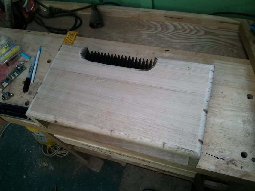
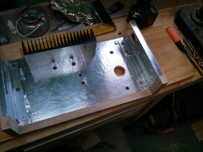
My final design was to sandwich the heatsink between the top and bottom of the case, with a cut-out to allow airflow over the fins. The front panel was also recessed by 15mm to help protect the switches and knobs as well. The case is made from planks of Australian hardwood called ‘Tasmanian oak’. It’s not really oak, but derived from a couple of different Eucalyptus species. Once the basic shape was cut out, I routed around the edges with a bull-nose router and sanded it smooth.
The electronics were to be bolted to the bottom of the case, with the top and sides being joined together to form a lid that goes over the whole assembly. The ‘lid’ bolts on to the bottom via M6 bolts through the sides into 3mm aluminium angle brackets with thread tapped into them. The walls seperating the different parts of the amplifier are to provide internal shielding against mutual interference and were eventually covered in copper tape.
The preamp goes in the front of the unit with the knobs and switches and is completely surrounded by grounded shielding to stop it picking up noise. Guitar preamps have massive gain, so they can easily amplify even minute unwanted signals into audible irritations. No-one wants to hear power supply hum or the local AM radio station through their speaker cab (or at all, really… ;).
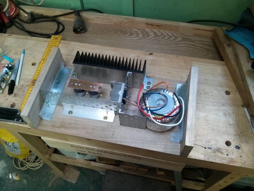
Once I’d worked out the positions of all the major components, I covered the insides of the box with aluminium foil to shield the electronics from extraneous interference. My approach is to use a dilute solution (approx 1:10, or even more, it doesn’t really matter as long as it brushes on really easily) of ordinary PVA woodworking glue.
Spread the glue across the wood with an old paint brush, apply the foil, smooth it down, and then use a sharp hobby knife to trim the foil just inside the edge of the wood panel. For connecting pieces, such as the side panels, the foil is folded around the inside edge so as it makes electrical contact with the top and bottom to form a continuous shield all the way around the enclosure.
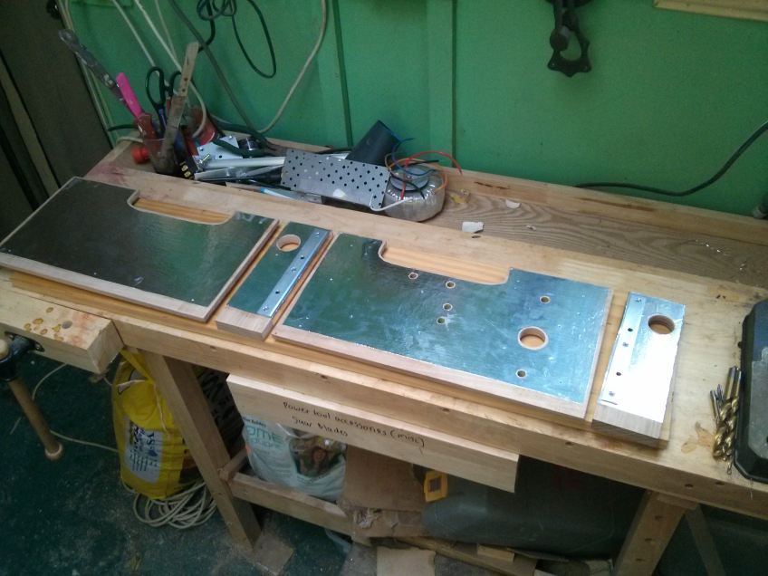
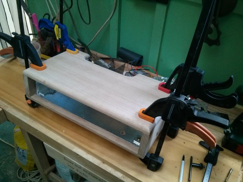
After marking, drilling and tapping M6 thread into the brackets that will bold the lid to the bottom, they were attached to the base and bolted to the side panels. Before the top could be attached to the sides, they needed to be aligned perfectly so that the whole thing would be square.
Once the sides were judged to be sitting perpendicular to the base, holes were marked and drilled for dowels to connect them to the top permanently and form the final cover assembly.
After the ‘lid’ was structurally done, it was time to stain the timber. I used a mixture of Jarrah (a red Australian hardwood) and Japanese Blackwood. I’ve seen a lot of comments on the net about the ‘right’ way to apply stains to timber. I just use a paint brush :/
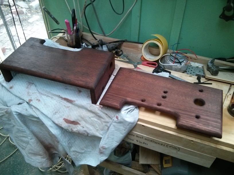
I was originally going to varnish the timber with polyurethane, but my partner suggested using shellac, which is what she uses on furniture. I thought it was a good idea since the amp will be moved around and isn’t supposed to look like a shiny ornament, so the shellac would give it a kind of ‘used, durable, hardwearing’ sort of look. Also, I’d never used shellac before, so it would be a good opportunity to try something new. Consequently, the timber has taken on some of the yellow of the shellac, which has really warmed the colour up. Many layers also give it a lot of depth and you get an almost holographic effect from the woodgrain when you rotate the piece in sunlight.

That’s it for this part, see part two for the internals and front and rear panels.