
P27 100W Guitar Amplifier Build
-
12 April 2016 |
-
15 September 2016 |
A two-part post on construction of my guitar amplifier. Part one here.
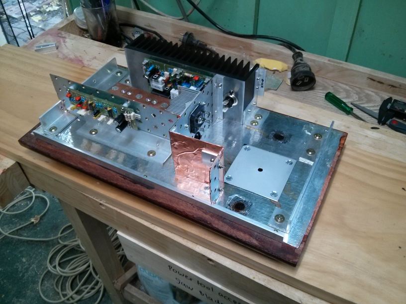
After the wooden part of the case was done, it was time to start assembling the internals. I’d already soldered the PCBs together - which didn’t take very long. The next step was getting them into the case.
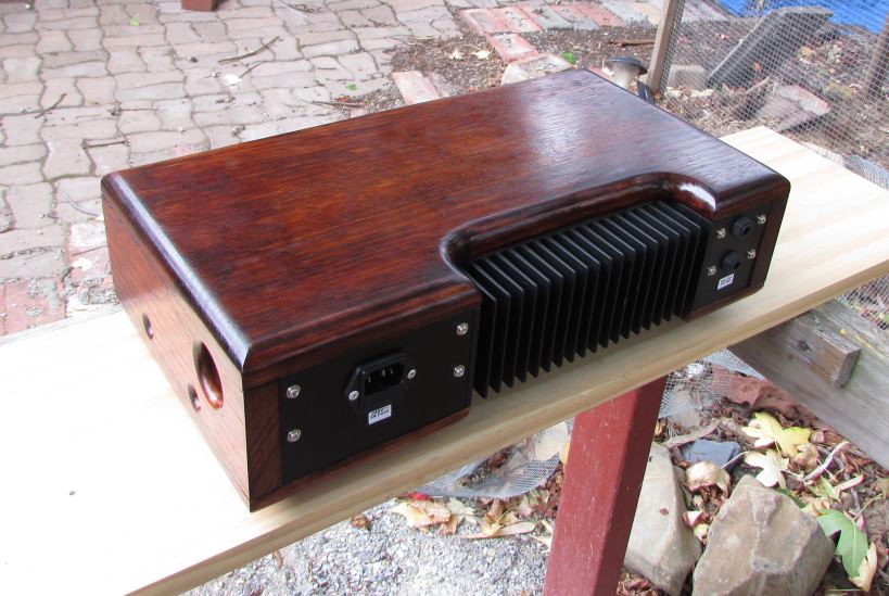
Since the heatsink was going to be sandwiched between the top and bottom of the case and took up a considerable part of the rear real estate, it became a structural member. I tapped threads into the outer fins to allow it to be bolted down to the bottom using brackets fashioned from right-angle aluminium. It also holds brackets for attaching the small rear panels that hold the power and speaker sockets, as well as the internal shield wall that separates the power supply from the rest of the amp.
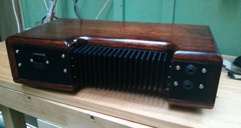
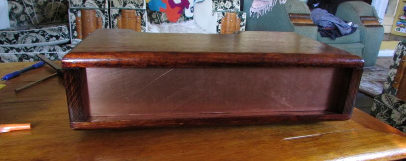
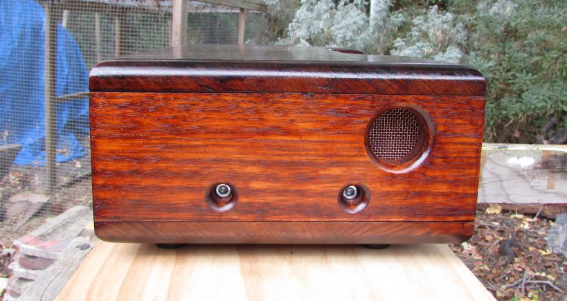
Time to fabricate the rear panels. Getting a good fit on these can be really annoying because no matter how much you use your set-square, the wooden parts never quite are - although in this case it’s to within a millimetre which is the best I’ve ever managed.
Anyway, in case people are interested in the methodology for getting flush metal panels with timber boxes, this is how I do it. Brackets to hold the panels are screwed to the supports and recessed by the thickness of the panel material (in this case 1.6 mm aluminium sheet).
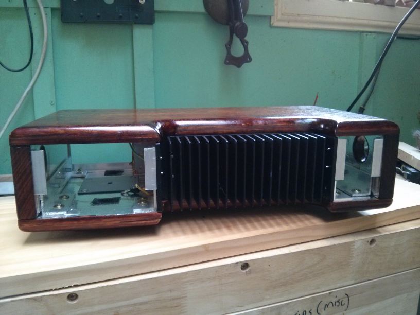
The case is bolted together so all dimensions are final (the timber flexes under load) and the gaps the panels will fill measured top and bottom, side to side. The material is cut just over a millimetre larger than needed, then brought back to the desired size using the precision grinding tool…
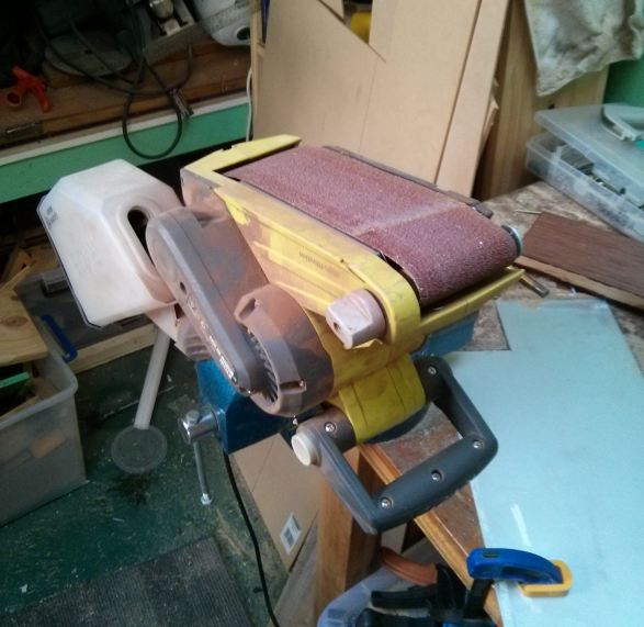
I do it this way because I don’t have any way of cutting accurate straight lines (I use a Dremmel, which is surprisingly good). It’s easier to grind some away to make the edges flat and straight than to add more material. The result is a perfect fit into the recessed cavities. I then drill holes in the panels which correspond with the brackets and use them as a template to mark the brackets for drilling and tapping with M3 thread. It was quite a fiddly job, but I think the fit and finish makes it worth it.
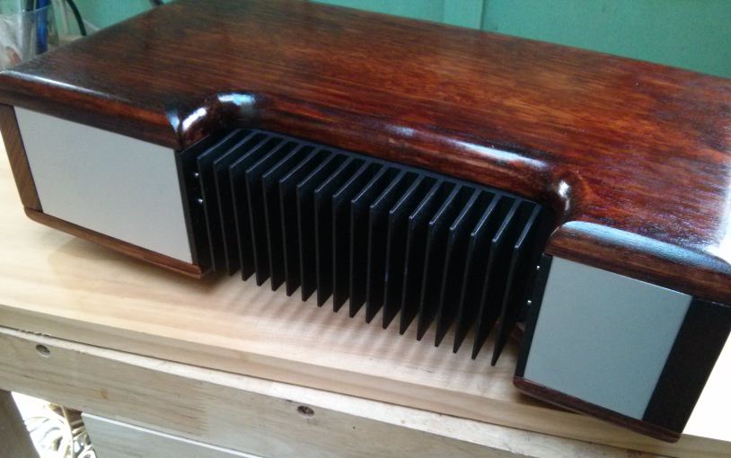
The panels then had holes drilled and cut to fit the power and speaker sockets before being given two coats of black spray paint, plus a clear coat for protection.
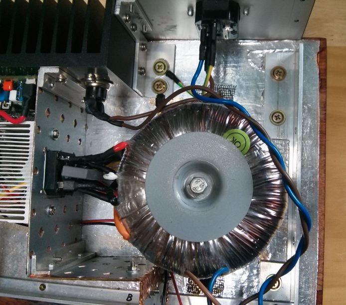
Next on the list was the power supply. I really needed to get the supply up and runnning, because I still hadn’t actually tested the circuit boards. At the time I didn’t have a proper bench power supply for testing, so I was relying on having the full amp supply to get it going. This is not really a good idea, as the full supply has no current limiting and is quite capable of vaporising components if there’s a board wiring error - but it all worked okay. (I’ve since made a bench supply, which makes life much easier).
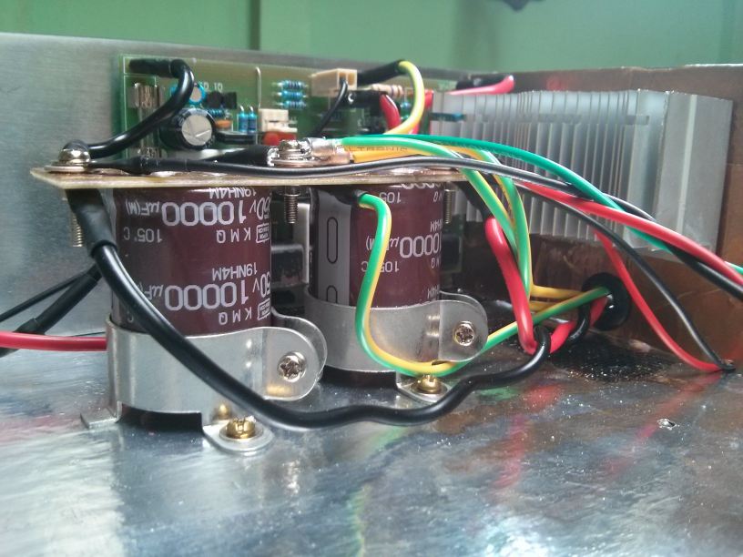
The raw DC goes through a hole in the shield wall to the main filter capacitors. The caps are joined via a piece of blank PCB that’s had lines cut into the copper layer to separate the ground from the positive and negative rails. M3 bolts hold the lugs to the board.
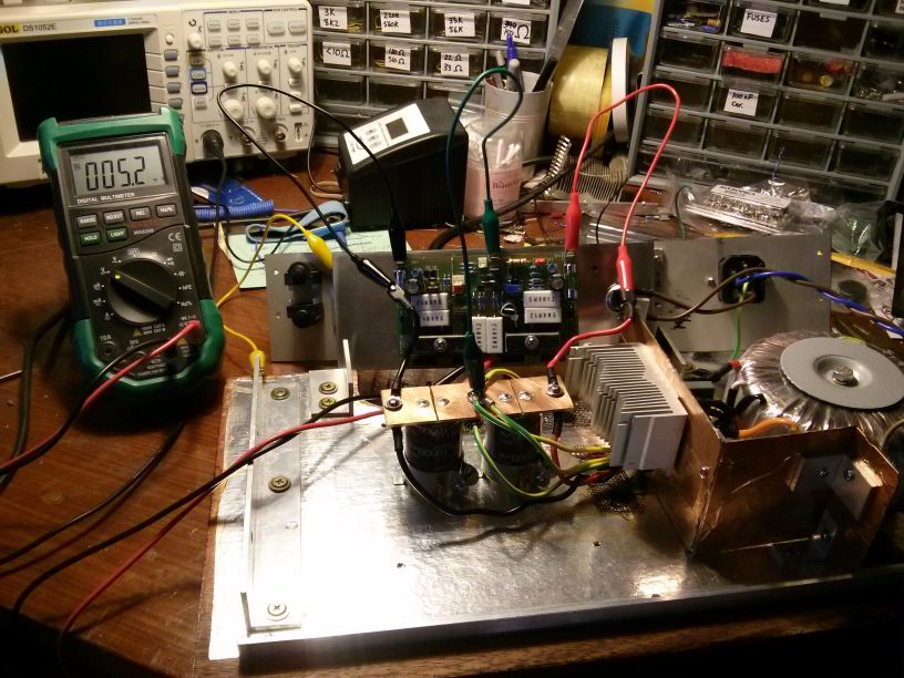
Once the supply was complete, I had to get the power amp up and running and set the bias of the output stage. This is an important step. Without bias, the amplifier will produce harsh-sounding crossover distortion as the signal goes positive to negative and is passed from one pair of output transistors to the other. Too much bias, and the output transistors will run hot as they burn up power that’s wasted heating the heatsink. Setting the bias is quite straight forward and you only need Ohms law to figure it out. However, you must remember to let the temperature of the heatsink stabilise at your selected bias setting, and re-check/re-adjust it if necessary.
The gain of the transistors changes with temperature and adding bias current dissipates power, warming the heatsink, causing the bias value to change. It will drift away from where you want it if you don’t take this into account. After setting the bias, it’s a good idea to use a drop of superglue to fix the adjustment screw into position so it can’t accidentally shift over time. A drop of nail polish will also do the job. In fact, nail polish is probably a better option because it’s easy to remove it with acetone if you ever need to re-adjust the bias (for example, if you have to replace the output transistors after a failure).
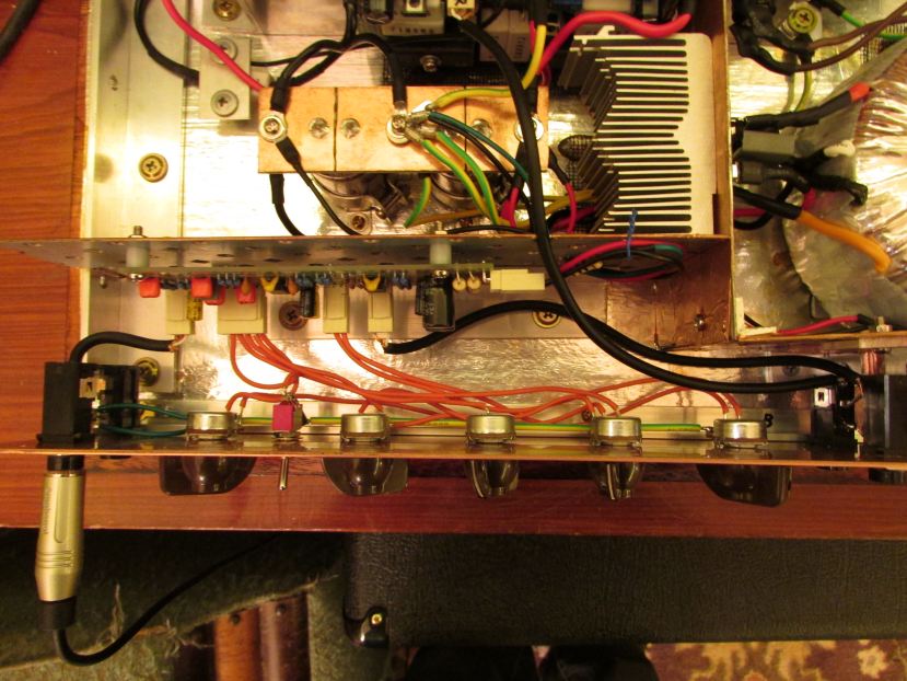
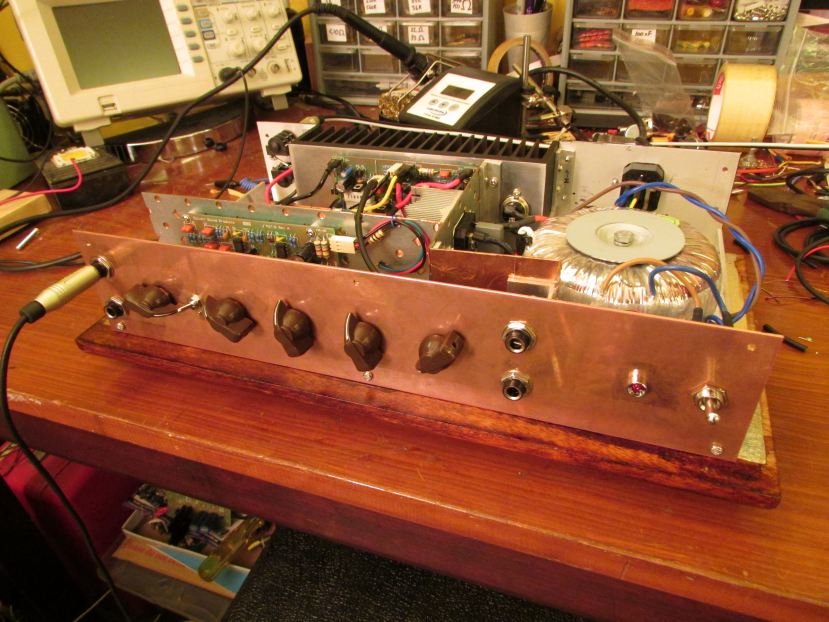
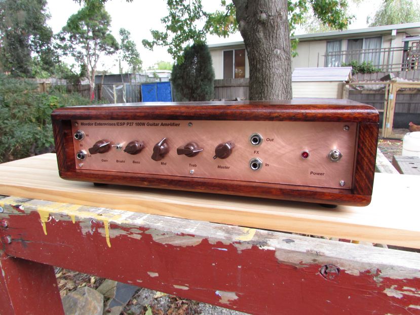
The last two tasks were making the front panel, and wiring in all the switches and knobs to the preamp board. I was going to make the front panel out of bronze, but after finding out how expensive it was going to be at the local non-ferrous metal dealer, I opted to use some of their copper offcut instead. I had it cut to size on site and checked to see that it fit nicely.
After some pretty ordinary front panels on past projects, I decided to spend some proper time designing this one. I wanted the knobs, switches and jacks to be evenly spread and look nice, but they also had to fit within the pre-defined boundaries of the preamp shield section. So, for the first time ever, I sat down and did a proper drawing with proper measurements to sort this out. Once I had a good template to work with, I drilled all the holes for the jacks, pots, switches and the M3 bolts that hold the front panel on to aluminium angle brackets which are screwed to the top and bottom of the chassis. Then I ran the wires from the preamp board to all the controls and attached the panel to the bottom of the chassis for some testing.
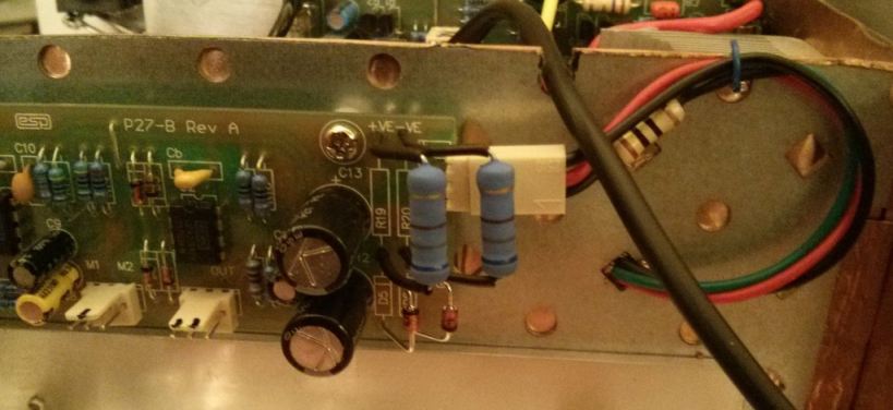
During testing, I noticed that the power supply section of the preamp was getting quite warm. The supply is a simple zener regulator that drops the ±35V of the main power amp supply down to ±15V for the preamp. It’s a linear regulator, which means it’s quite inefficient (but will inject far less noise into the analogue circuit than a more efficient switching buck converter). A pair of 1W dropper resistors were dissipating ~0.7W each and were way too hot to touch. Although technically within ratings, they were also causing some nearby electrolytic capacitors to get quite warm as well. Heat shortens component life, so I decided to replace the 1W resistors with 3W ones and mount them further off the board to move them away from the caps and allow more airflow to keep them cool.
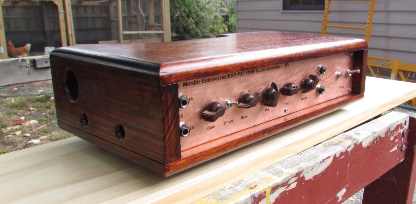
And that’s about it. I just had to prettify the front panel, put it back together and it was complete. I tried buffing the front panel to a mirror shine, but I couldn’t get a clear coat of paint to stick to it while it was so smooth, so I used 1200 grit sand paper to cut a nice pattern of cross-hatching with swirls onto it. I made labels with a label printer, stuck them on and put a clear coat over them as well so they won’t peel off and the amp was finally finished!
So how does it sound? It’s a difficult question to answer, given that guitar amps are so personal. Doubtless there will be people that hate it, but I quite like it. Clean, it’s quite warm. Over-driven, it certainly has character - although that wouldn’t be to everyone’s taste. I have found that I much prefer to use pedals to get distortion effects and then run them into the amp set clean (but that might be my recent obsession with playing NWOBHM talking ;). It has oodles of power to spare as well as a wide tonal range, so it’s certainly worth experimenting.
The ability to experiement to get exactly what you want - rather than what some big gear manufacturer tells you you want - is one of the great things about building it yourself. You can fiddle with the tone stack component values, play with the clipping diode arrangement, etc. For me, however, the best part was the ability to ensure I had NO HUM and NO BUZZ! All that shielding was well worth the effort. I get more noise from the pickups in my guitars than the amp itself. Great! :)