
Death of Zen Class A Headphone Amplifier
-
11 October 2021 |
Having never listened to a class A amplifier before, and with nothing better to do during the long Covid shutdown, I thought it might be nice to build one. The circuit is another of Rod Elliott’s designs: the low-power headphone variant of the “Death of Zen” class A power amp. There’s quite a bit of history to this circuit, which Rod explains in the original project article. It’s well worth a read if you’re at all curious about the design decisions or class A in general.
Class A amps are well-suited to headphone use (insofar as they can be said to be well-suited to any practical applications at all). The wasted power, which can become a serious problem for larger systems, is very modest at headphone levels and easy to deal with. Given how revealing a good pair of headphones can be, having an amplifier that is immune to at least one type of distortion is something worth thinking about.
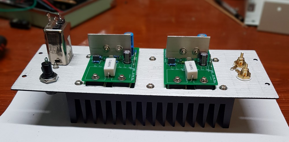
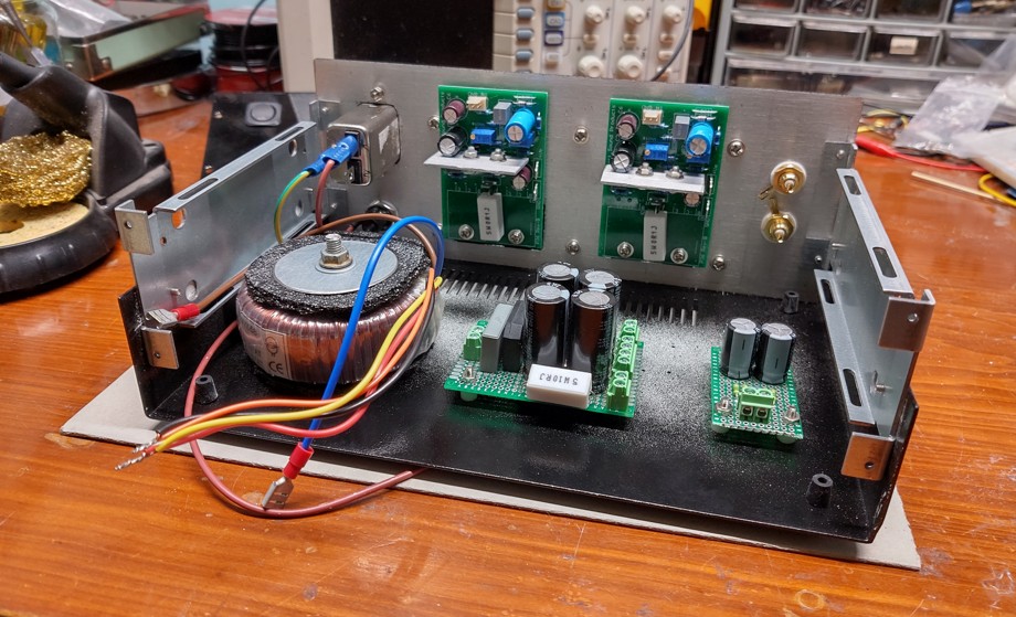
As per usual, I bought the bare boards for the amp modules themselves from Rod’s site (board sales help pay for hosting, and it certainly eases construction). The power supply and other smaller boards for mounting the volume control and final DC blocking filter were cobbled together on prototyping board.
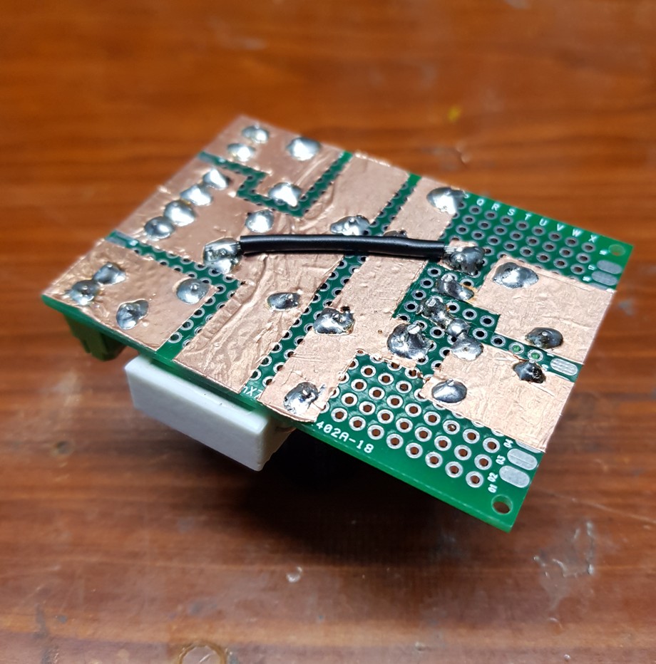
To speed up constructoin a bit, I used a subtractive technique to lay the tracks down on the power supply board. Power supplies are simple and generally require thick tracks, so this works quite well for them. You stick a piece of copper foil to the underside of the board, mount the components, then use a sharp knife to remove unnecesary copper to create the tracks.
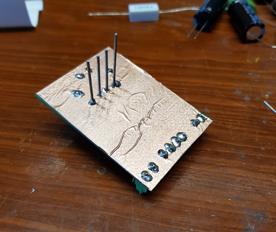
The down side is that soldering can be difficult with all the extra copper sucking the heat out of your iron, so you may find it easier to cut the tracks as you go.
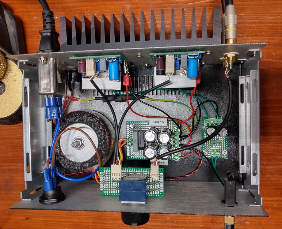
Assembly of the rest of the amp was straight-forward, but testing turned out to be more difficult than I was expecting. The design specifies 100k multi-turn trimpots on the amp modules for setting offset voltage and bias current. Personally, I found that these needed to be lowered to ~50k to allow me fine enough adjustment to get the amps to stabilise.
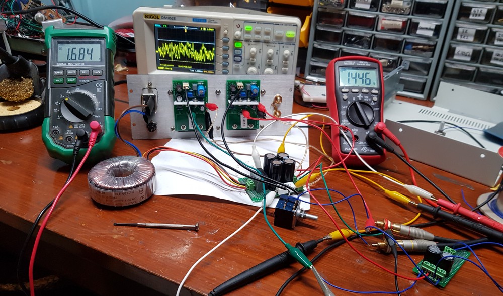
Before then, I found they drifted around a lot (which is fine, a circuit like this is bound to drift around with temperature). The problem was getting them to drift together and to keep it within an acceptable envelope. Once I lowered the value of the trimpots, I had no problem setting them and getting them to track close together.
The cases for a lot of my projects over the years have been made of wood, mostly because I’m not very good at metal work. I purchased a pre-made steel case with aluminium front and rear panels for this project as I thought it might make the whole process a little quicker and easier. This turned out to be a bit of a mixed bag :)
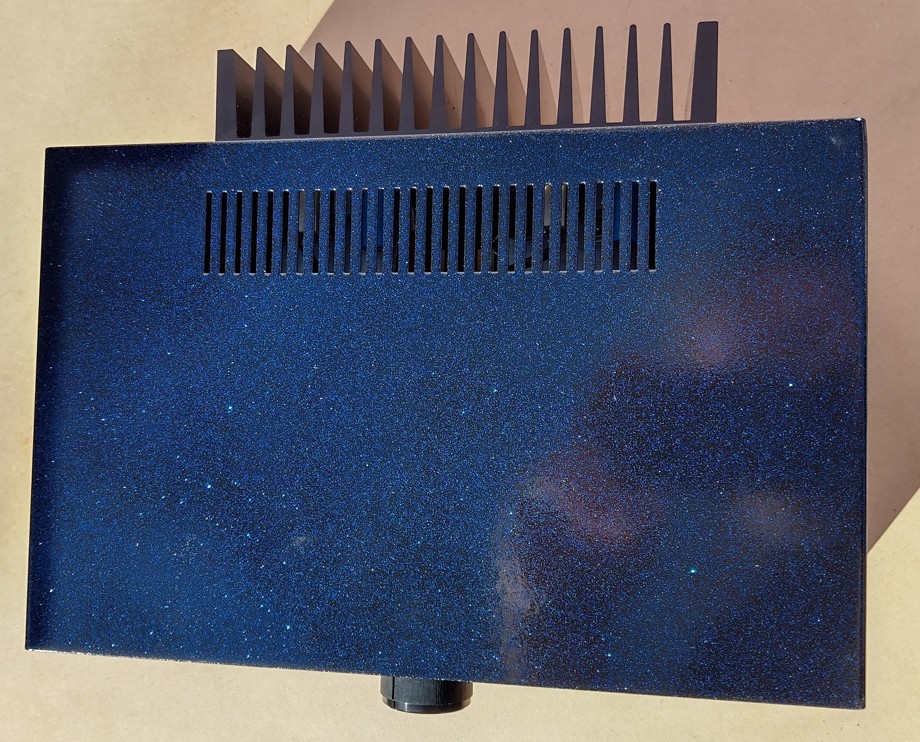
Marking and drilling the front and rear panels of the case was a breeze, but painting it turned out to be a real pain in the backside. I had a lot of problems with runs and various other surface imperfections. After doing too many coats, I managed to make it look it look vaguely acceptable, but not really what I had envisaged in the first place.
I underpainted in black gloss (a mistake, gloss shows up every little imperfection, but I wanted the base layer to reflect as much light back through the top coat as possible) and over-painted with a highly metallic colloidal blue. The effect over black is (or rather should be) quite striking. But after too many coats trying to fix various problems, it doesn’t look as good as I’d like it to. However, I’m far too lazy to strip it back and start again. It’s good enough.
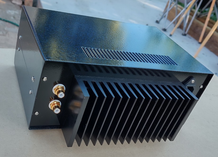
In addition, it’s really difficult to get a half-decent photo of it because it’s far too glossy and shiny. I’ve learned my lesson and I won’t bother with gloss again. There is no way I can get a shot of it on my electronics work bench, as there are far too many pin-point directional light sources there, so I took it outside during moderately overcast conditions to see if I could get a few passable photos.
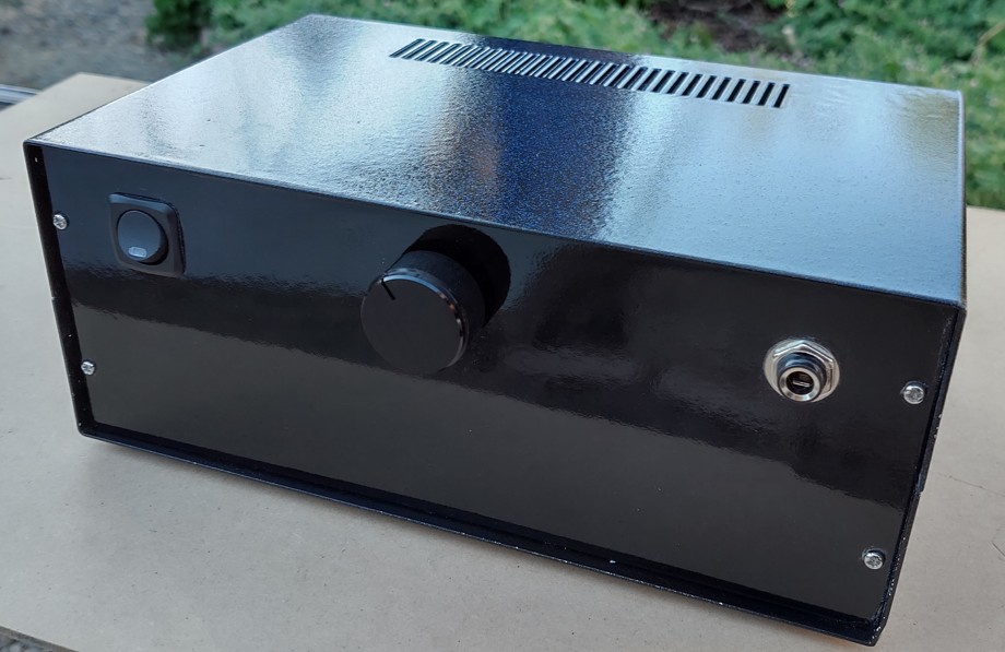
One aspect where it does excel is sound. It really does sound great; it’s so clean. I have no measurements to back up any claims here, so I’ll leave it at that. I think it was worth the effort, though. Even if I don’t use it as often as my P113 (which is attached to my computer), I’m glad I made it.
It’s nice to have a headphone option out in the main “listening room” so you can enjoy great sound without disturbing anyone.