
P113 Headphone Amplifier
-
27 January 2014 |
-
15 September 2016 |
For a short time when I was working at a university, I was working three jobs on campus at the same time. A small wad of disposible income burning a hole in my pocket, I cast around for something to spend it on. My old headphones, Sennheiser HD575s, had done me very well for over a decade by this point, but the wear was starting to show as they were beginning to fall apart. So I thought it might be time for an upgrade. I went and listened to a whole bunch of high-end ‘phones and eventually settled on a set of Sennheiser HD800s. They totally. Freaking. Rock. Extraordinarily revealing and solid. No pretense at being ‘good’ at bass, or whatever, just clear sound. They are rather pricey, though…
Anyway, having purchased the ‘phones, I found myself needing an amplifier to drive them. They have a nominal impedance of 300 Ohms, so you can’t just plug them into an iPod. They need real power from a low-impendance source. Being a fan of Rod Elliott’s easy-to-build amplifier designs, I decided to build a P113 headphone amplifier.
It’s a fairly straight-forward, yet flexible design; centred around a dual-channel opamp, with its output current capability boosted by a pair of medium power transistors. Together they provide all the grunt you’ll ever need to power a set of headphones. You can quite easily run several pairs at once from one amp. In fact, I sometimes use the amp to drive a pair of crappy bookshelf speakers on my desk when I don’t feel like wearing the ‘phones.
The board was purchased from ESP and I attached it to a power supply board I built that’s based around Rod’s P05 small linear supply. I had about ten copies of this board made ages ago because I always seem to need small power supplies. The supply is powered by a 16V AC plug-pack, so there’s no transformer in the case, meaning no stuffing around with the mains and no power supply hum. Too easy.
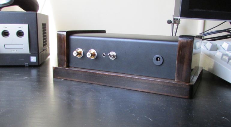
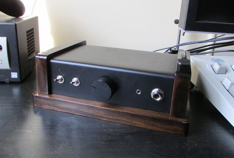
The case is made from a 1.5mm thick piece of aluminium sheet, bent into a ‘U’ shape to form the main cover. Four coats of matte black, followed by four coats of ‘satin’ clear coat spray paint have given it an almost professional powdercoated look. To cap the ends of the aluminium cover and provide a base plate, I used pieces of pine, sanded to round off the corners, then stained with a mixture of cherry red and Japanese blackwood before finishing with five coats of polyurethane. The end-caps where then glued to the ‘U’ section and the whole thing screwed down to the base.
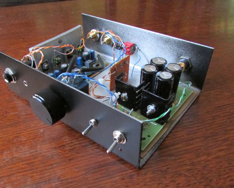
Unfortunately, due to space constraints, I had to glue the boards into the aluminium U with cardboard underneath them as an insulator. If I’d been smart, I’d have used velcro so I could take them out again easily. But I wasn’t ;)
I also added a crossfeed circuit on a piece of veroboard and a switch on the front panel to switch it in and out of circuit. I’ve played around with a couple of these and never really got any of them to sound any good, so I leave it switched out permanently now.
It’s a great-sounding amp. And by that, I mean it doesn’t appear to colour the sound at all, it’s just the music and nothing else. At the time, while this was under construction, I was using an old home theatre receiver to drive the HD800s and the difference was night and day.
I’ve since added another ESP project board to this amplifier: a P33 speaker protection and muting circuit. This mutes the output for a couple of seconds after switch-on so I don’t have to hear any pops as the amp stabilises. It will also disconnect the output from the amplifier should it detect a DC fault. This can occur if the amplifier fails and outputs a power supply rail to the drivers. In that case, you’re in very real danger of killing your expensive headphones, so it’s well worth the small investment. In my case, it might only warm up the voice coil (I=V/R I=15/300 I=50mA. P=VA P=15x0.05 P=0.75 Watt.), but I’d rather not take the risk :)