4-Way Stereo Input Selector
-
12 July 2026 |
I created this 4-way stereo input selector module becuase I needed an analogue stereo input selector for a couple of audio projects I had in mind.
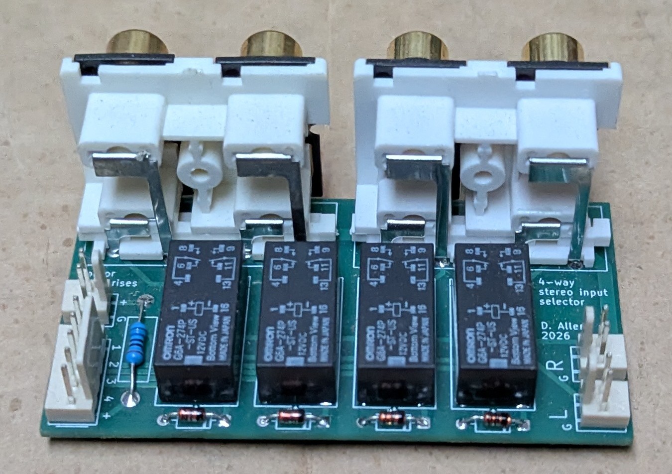
The design for the board is open source and free for anyone to use. It was designed in KiCad and both the gerber and KiCad project files are available on Github. You’re free to copy these and modify the board if you want, or to simply send the gerber files to your favourite PCB fab and get it manufactured.
Rationale
I don’t mind using rotary switches to select the input, but I don’t like running signal cables forward to the switch on the front panel, nor do I like using extension shafts and locating the switch at the rear of the enclosure because it means I have to plan ahead too much for internal layout.
This board uses relays to select the desired channel, which means it can be switched electronically or manually using a rotary switch, but without the hassle of running signal lines to the switch itself. In this case, the switch simply selects the appropriate relay and that ensures the desired input is connected, which considerably simplifies the internal wiring.
How it works
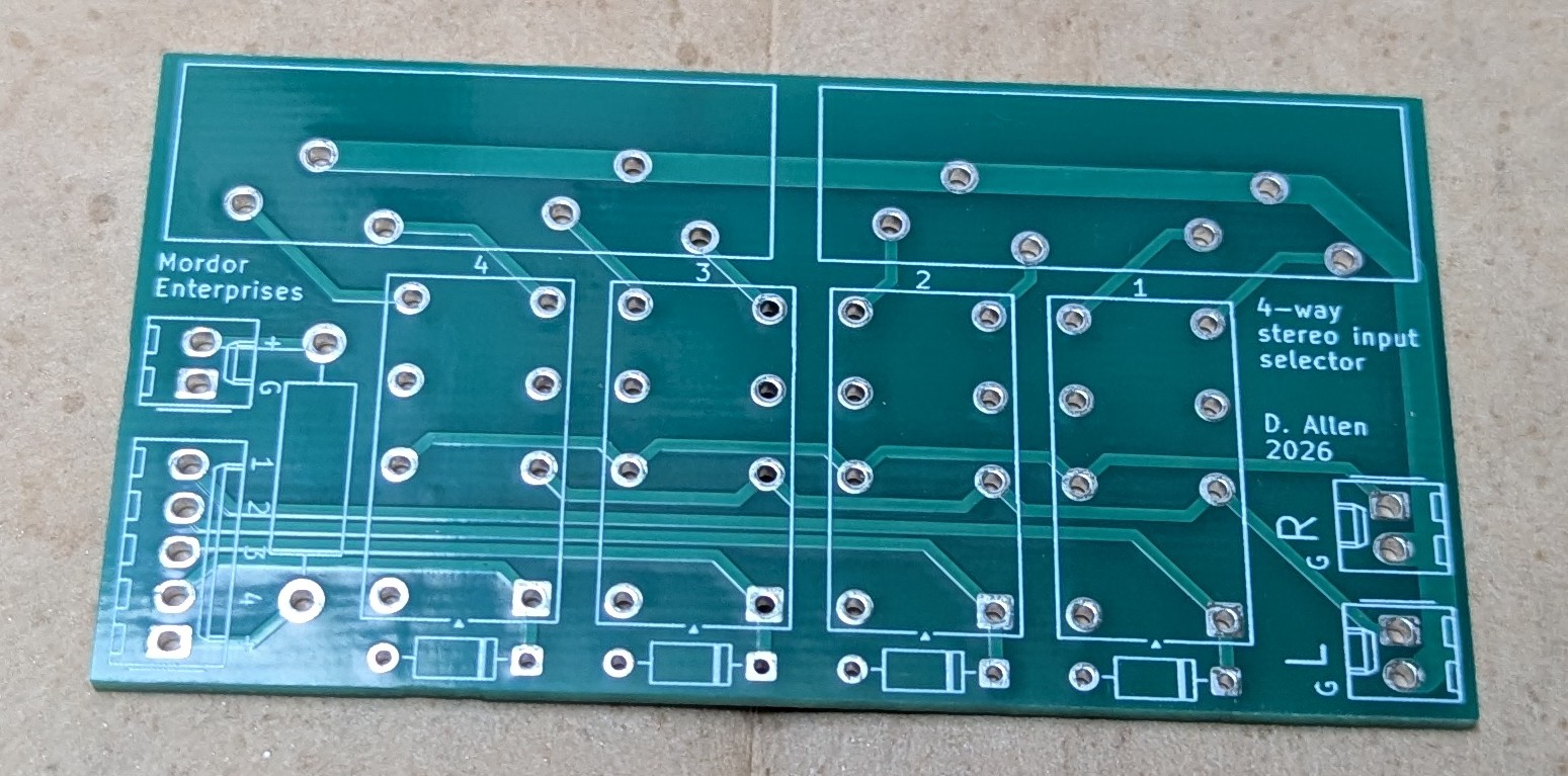
The top left header is for relay power and ground. This passes through resistor R1 before appearing on the second header. I’ve intentially not specified a value for this resistor as it is meant to drop your rail voltage to whatever coil voltage you need for your relays. You can replace it with a wire link if no dropper-resistor is required.
The second header goes to your switching solution, whether that be a manual rotary switch or electronic equivalent. The switch should connect the positive rail to the relay of your choice, which will then close and connect its RCA sockets to the output pin headers on the right-hand side of the board.
Implementation notes
- The board requires full-current drive for the relays. This board is not suitable for using low-level switching signals to drive the relays. I intentionally did not include space for a transistor to drive each relay coil to save space (and because it was not required in my projects). There’s nothing stopping you from doing this yourself elsewhere in your project, just be aware of this limitation.
- The relay power ground and analogue signal grounds not connected on the board. You can do this yourself if required by simply soldering a wire link between an RCA ground pin and the board ground plane, but I opted to keep them separate for maximum flexibility.
- The board was designed for G6A relays, but any small signal relay with an equivalent footprint can probably be substituted. Note that these are often polarised to reduce drive current, so take care to ensure correct coil polarity.
- The board was designed to accept PHS-14B-style PCB-mount RCA sockets.