
LED Strip Room Lighting
-
14 January 2017 |
-
16 January 2017 |
In January of 2015, I built an LED lighting controller and power supply to run about 25 metres of 12V 5050 LED strip lighting. The strip forms a ring around our back rumpus/listening/hobby room. The lights are mounted high up the walls only a few centimetres down from the cornices on L-shaped pine moulding, with the LEDs facing the ceiling so as not to dazzle the eye. It’s meant to light the room with a soft warm-white glow around the perimeter to provide a mellow mood for hanging out listening to the stereo, or during parties, etc.
Initial Build
The plan was fairly straight-forward: buy the LED strip lights, a beefy 12V supply to run them, and use an ESP P126 PWM dimmer to allow control of the light level. Then, string them together and enjoy. Needless to say, the project became a little more complex as time went on, and I learned some valuable lessons along the way.
The first mistake I made was to buy a crappy 360W 12V supply from ebay. These supplies do not have a very good reputation for longevity, and I opted to go with one that provided more power than I actually needed in the hopes that the added headroom would make it last a little longer.
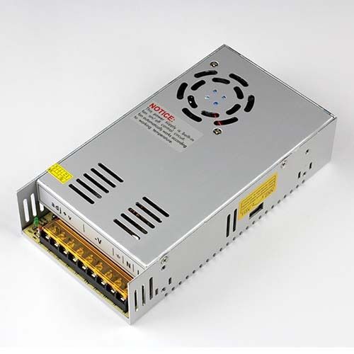
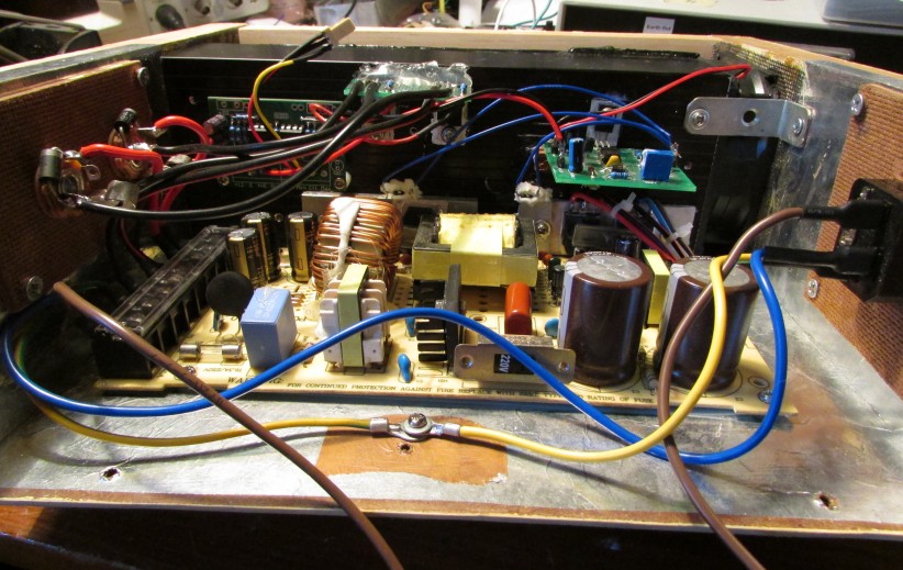
After the supply arrived, I pulled it apart to find several very good reasons why these supplies are not well regarded. Completely inadequate thermal management of the switching transistors and high-current rectifier diodes (bolted straight to the case, very poor thermal contact), low quality electrolytic capacitors, and a whiny 60mm fan completed the picture. This project being done on the cheap, however, I decided to press on and see if I could make it work regardless.
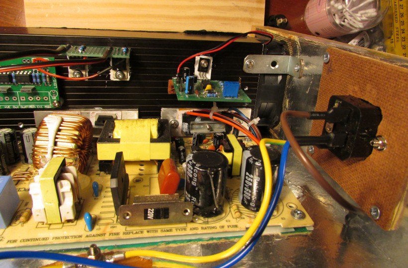
I decided to attack the thermal problems first. I moved the main switching transistors from the rear of the board to the side and mounted them, along with the secondary side rectifier diodes, to half an 80mm tunnel-style heatsink. This heatsink is quite large and has a thermal resistance of ~0.8 °C/W without fan assistance.
Given that this supply was to be mounted in the same room as the stereo, I wanted it to run without a fan unless absolutely necessary. A piece of PVC pipe was used to complete the tunnel on the other side of the sink and a quiet 80mm fan was mounted at the bottom end to blow air up through the heatsink tunnel assembly should the temerature rise too far.
The fan is controlled by a P42 thermo-fan switching circuit I made quite some time before. The circuit works by sensing the voltage across a couple of ordinary silicon diodes. As the temperature of the P-N junction in a diode rises, the the voltage across it falls. A 741 opamp wired as a comparitor monitors this voltage and compares it with a fixed reference.
Once it hits a certain level (which you set when you calibrate the circuit), the output of the opamp flips and goes low, turning on a PNP transistor that then switches on the fan. In this case, I used a glass of warm water to help me set the circuit to turn the fan on when the heatsink reaches ~45 °C. It almost never turns on except for hot days.
The P126 PWM dimmer circuit connects the power supply to the lights and allows adjustment of the brightness of the LEDs via a single 10k potentiometer. The circuit uses a couple of dual opamps to provide the PWM function. Two are set up to form a triangle wave oscillator with a frequency of around 400Hz. A third is wired as a comparitor, and just like in P42, compares the voltage of the triangle wave with the reference voltage across the 10k pot.
When the value of the triangle wave is lower than the reference, the output of the comparitor goes high and switches on a power MOSFET to allow current to flow in the lights and vice versa. By changing the value of the 10k pot, you change the reference voltage, which alters the duty cycle of the MOSFET and hence the average brightness. Check out the project article for a more detailed explanation as well as a circuit diagram.
Unfortunately, the only MOSFETs I had to hand were a few IRF540s, with a current limit of 27-33A (depending on whose datasheet you’re reading). The number of LEDs to be powered would need over 20A at the brightest setting and would push a single device towards the edge of its safe operating area. To solve this, I decided to split the room light ring into two halves and use a separate MOSFET to power each half. One drives the back wall and one side, the other drives the front wall and the other side.
This turned out to be a good idea because it halves the current through each MOSFET, doubles the thermal transfer area of the MOSFETs to the heatsink, halves the total current flowing through the main power cables to the LEDs (since there are now two pairs instead of one), and reduces the voltage losses across the cabling as well as cable width requirements. This lunch is not free, but for the small cost of an additional MOSFET, connector, and an extra 2m of cheap speaker cable, it comes heavily discounted :)
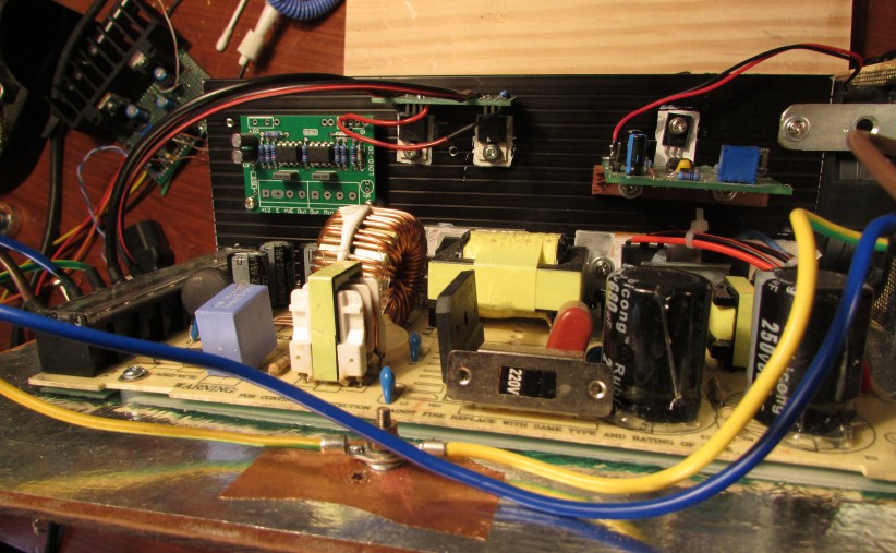
The P126 PWM MOSFETs are mounted off the board directly on the heatsink, with a small daughter-board made of prototyping board used to provide a mounting point for the heavy power cables and gate resistors required to damp ringing of the control signal from P126.
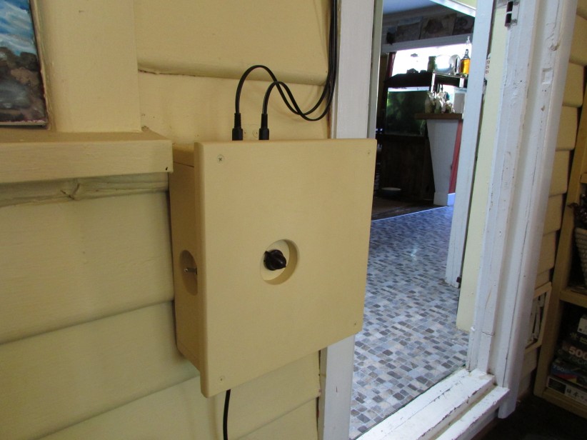
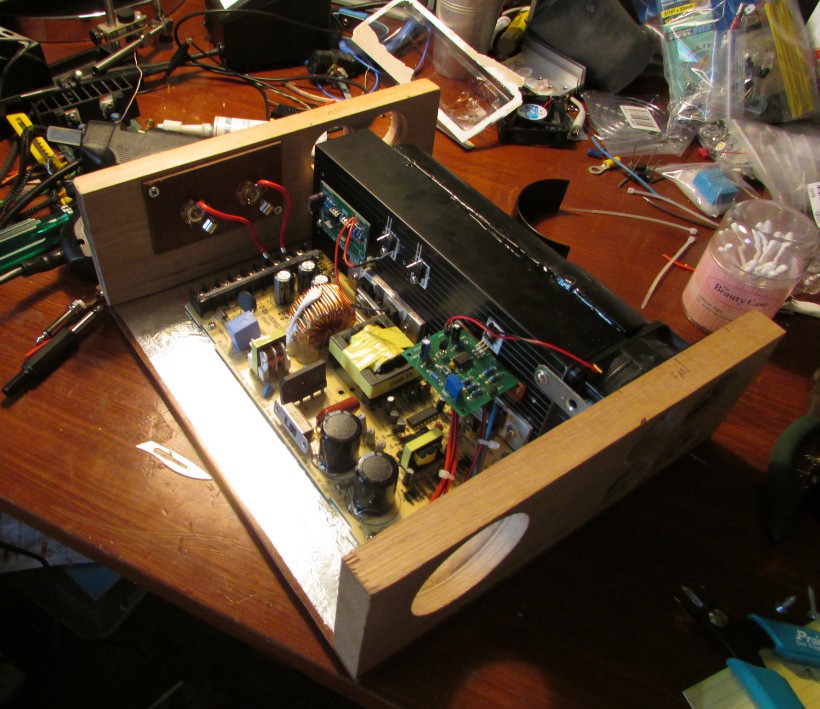
The unit is built into a wooden box made of pieces of pine and Tasmanian oak off-cuts. The inside is lined with earthed aluminium foil to help sink EMI. Connections to the outside world are via holes drilled in the wooden panels with a hole-saw. The connectors were then mounted onto a thinner piece of material (such as aluminium sheet) and then screwed to the panels behind the holes.
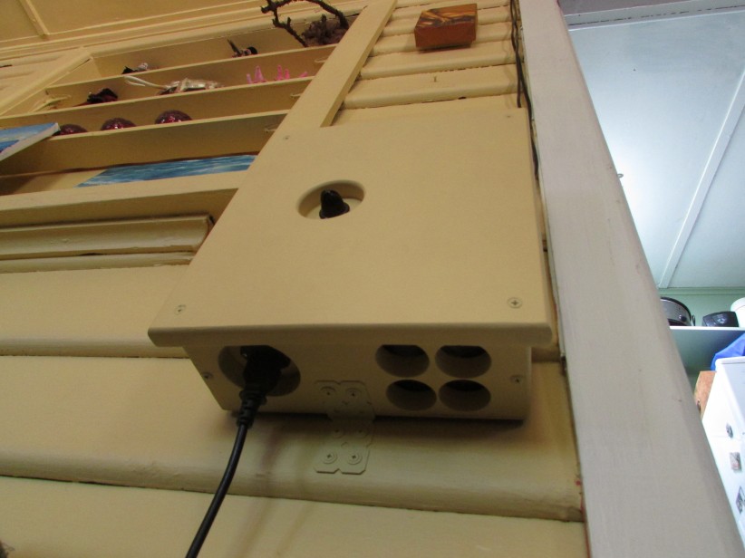
The vent holes in the top and bottom of the case were covered in flywire to stop insects and inquisitive fingers from making their way into the box. It wasn’t strictly necessary because the heatsink blocks off the high-voltage side of the box from the vents, but it seemed like a good idea nonetheless.
Repair
The project worked well over a year, but failed one night without much fanfare. The lights gave a flicker, the supply made a funny noise, and then it all went dark. I pulled it apart the next day to discover that the main filter capacitors on the primary side of the supply (“Rubycong” knock-offs of Rubycon) had failed. These caps were rated at 250V 680uF. One measured 420uF, the other 16.7nF. I decided to replace all the electrolytics in the supply with high quality ones - which is something I should have done when I first built it.
The primary filter caps were replaced with legit Rubycon 250V 560uF, the closest value I could get with the same footprint. The output filter caps on the secondary were replaced with Panasonic high performance, low ESR caps specifically designed for high-current switching supply filtering. I also replaced all the small electrolytics in the control circuitry, although this probably wasn’t really necessary, so they just got cheaper Lelon low ESR parts.
After putting it back together, the supply refused to start. I found this puzzling as there were no other obvious signs of damaged or failed parts. Thus the great trouble-shooting saga began. This was hampered by the fact that I couldn’t connect most of my test gear to the supply becuase most of it runs at mains potential and I don’t have any isolated probes for my oscilloscope. I wasn’t going to risk killing the ‘scope on a cheap supply, so I was stuck with a multi-meter and my brain.
I probed around with the multi-meter set to DC volts and did some reverse-engineering on the primary side of the supply. It turns out that this supply is a very old half-bridge design. After a bit more reverse-engineering and probing, I discovered that the main control IC was not getting any power. I traced out its supply and found that it came from an auxillary sense winding on the main transformer. This suggested the transformer wasn’t doing anything. Lo and behold, one of the main switching transistors driving the primary coil measured ~300 ohms from collector to emitter, rather than the many mega-ohms it should have been.
This was surprising for a couple of reasons: firstly, I expected to find MOSFETs as the primary switching transistors, not high-voltage NPN devices. Secondly, I would have thought that if a transistor was going to fail in this application, it would fail properly short circuit and read almost zero ohms from one side to the other, not this weird half-way value. Still, live and learn and all that :)
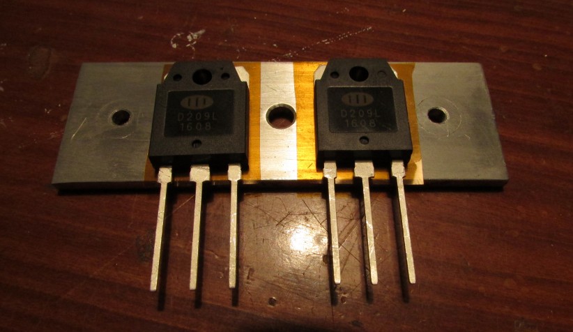
Anyway, I ordered a couple of new D209L transistors and replaced the old ones. This was a very fiddly job due to the nature of the lightbox and the way I originally built it. The transistors and diodes are attached to the main heatsink via heat-spreading aluminium plates salvaged from the original power supply chassis. The way these are mounted makes accessing them through the other components on the board very difficult.
Still, after replacing these transistors, the supply is now working again. However, it is now making a mildly irritating whining noise. I believe this is due to magnetostriction. Although it used to make a little noise when I first built it, it’s now quite a bit louder, so I’ll have to figure out a way of damping it.
Lessons Learned
Number one: never buy another one of those crappy ebay supplies. The designs are ancient, the construction is not good and the components are complete crap. You get what you pay for :) In my defence, at the time I bought it, I didn’t know anything about good supply manufacturers like PULS and the like. Next time, do more research!
Number two: switchmode supply design. I learned quite a bit during my reverse-engineering of this supply and the background reading I did in support of it. That, in part, makes the saga worthwhile I guess.
Number three: When (not if, but when) this supply fails again, I’ll probably just replace it with two good quality “lump-in-the-cord” power bricks, each powering half the lights. This seems like a much easier and less fiddly solution than re-engineering ebay junk.